Most administrators handle printers in very different ways. My personal favorite (works with MS DHCP and ISC DHCP) is to:
1. Assign a static DHCP based IP address for the printer in DHCP, and call it lpt-name_of_printer. (i.e., lpt-marketingcolor01 is the reservation 00:11:22:33:44:55 has for 192.168.78.51)
2. Set up a DNS entry for it (lpt-marketingcolor01.mydomain.local as an A record for 192.168.78.51)
3. Create the printer on the print server, using the fully qualified hostname as the address (or in MS parlance: creating a new port -> standard TCP/IP -> use the fully qualified hostname.
The advantage of this is that if you need to renumber printers, you simply need to modify the reservation and the DNS entry, not the actual printer. Some printers do support supplying a DHCP hostname, but with this method, you have more control.
Tuesday, April 5, 2011


Sunday, March 27, 2011
Bricked Linksys WRT54GS v1.1
I recently managed to pseudo brick an old Linksys WRT54GS (the specifications of the various WRT54 series wireless routers are here : Wikipedia article
Anyway, I accidentally broke it with an OpenWRT update that went badly. I did not want to have to create a Jtag for it, if I could avoid it. I tried a 30/30/30 reset. That failed. The router would power on and the DMZ light would turn on for five seconds and then turn off. This continued indefinitely.
After looking it, up it appeared that the boot loader was working, but that the firmware image was missing or corrupt. I followed the advice I found on several locations:
Attempt to push the stock Linksys firmware to the device using TFTP. It looked like the simplest way to do that would be to use the DrayTek Vigor router tools. Specifically, I used their "firmware upgrade utility." It worked on the first try. It's a simple process:
I set the ethernet interface on my laptop to be on the stock 192.168.1.0/24 network. I could ping the host with no problems.
I pointed the firmware upgrade utility to the latest official Linksys/Cisco firmware for the WRT54GS hardware version 1.1 router.
After the router rebooted, I had the stock firmware running on the default address (192.168.1.1) with the default password (no username, admin as the password.)
I later installed DD-WRT using the built-in Linksys firmware update page. DD-WRT. I could have used Tomato or OpenWRT again, but I wanted to try out DD-WRT. I'll likely write a post or two about my experience with DD-WRT.
Anyway, I accidentally broke it with an OpenWRT update that went badly. I did not want to have to create a Jtag for it, if I could avoid it. I tried a 30/30/30 reset. That failed. The router would power on and the DMZ light would turn on for five seconds and then turn off. This continued indefinitely.
After looking it, up it appeared that the boot loader was working, but that the firmware image was missing or corrupt. I followed the advice I found on several locations:
Attempt to push the stock Linksys firmware to the device using TFTP. It looked like the simplest way to do that would be to use the DrayTek Vigor router tools. Specifically, I used their "firmware upgrade utility." It worked on the first try. It's a simple process:
I later installed DD-WRT using the built-in Linksys firmware update page. DD-WRT. I could have used Tomato or OpenWRT again, but I wanted to try out DD-WRT. I'll likely write a post or two about my experience with DD-WRT.
Thursday, February 10, 2011
Upgrading Cisco Catalyst Switch Firmware Using Archive Command
I had to upgrade some old Cisco Catalyst switches to the latest firmware. The problem was that the flash contained the old firmware... and the delete command did not seem to honor the /r/f flags (at least in this old version from the year 2000.)
To clear out the html dir on the Cisco switch:
delete /force /recursive flash:html/*
Assuming my tftp server's IP is 172.18.27.40 and I have a cisco firmware tar file called "c35xx-new-version.tar" in the root of the tftp server, I upgrade like so:
archive tar /extract tftp://172.18.27.40/c35xx-new-version.tar flash:
(or archive tar /xtract tftp://172.18.27.40/c35xx-new-version.tar flash: - depending on version)
(later versions of IOS use the flag /xtract instead of /extract.)
As always, try this at your own risk.
To clear out the html dir on the Cisco switch:
delete /force /recursive flash:html/*
Assuming my tftp server's IP is 172.18.27.40 and I have a cisco firmware tar file called "c35xx-new-version.tar" in the root of the tftp server, I upgrade like so:
archive tar /extract tftp://172.18.27.40/c35xx-new-version.tar flash:
(or archive tar /xtract tftp://172.18.27.40/c35xx-new-version.tar flash: - depending on version)
(later versions of IOS use the flag /xtract instead of /extract.)
As always, try this at your own risk.
Thursday, January 27, 2011
Checkpoint UTM Firewall Clusters Part 4 - NoNAT Rules
Cisco ASA administrators will be well familiar with noNAT rules... those NAT ACLs listed under NAT 0. It's a similar configuration for the Checkpoint. Using the network groups I created in part 2 of this series,
Checkpoint UTM Firewall Clusters Part 2: Anti-Spoofing
One can create individual NoNAT rules like so:
To prevent NATing between the corp_net (192.168.6.0/23) and the DMZ, you can create a pair of rules (make sure they are above your implied rules!):

Of course, you might want to avoid any NATing between internal VLANs/subnets. Using our previously created simple group, inside_networks (it contains corpnet, eng_net, qa_net, and router net):

That should do it.
Checkpoint UTM Firewall Clusters Part 2: Anti-Spoofing
One can create individual NoNAT rules like so:
To prevent NATing between the corp_net (192.168.6.0/23) and the DMZ, you can create a pair of rules (make sure they are above your implied rules!):

Of course, you might want to avoid any NATing between internal VLANs/subnets. Using our previously created simple group, inside_networks (it contains corpnet, eng_net, qa_net, and router net):

That should do it.
Checkpoint UTM Firewall Clusters Part 3 - Overloading NAT and PAT, Proxy Arp
In this instance, we're going to cover a 1 to 1 NAT (a bi-NAT) and an overload of a single port for the same address. Refer to the first part in this series to get a better idea of the topology:
Checkpoint UTM Firewall Clusters Part 1
In this case, we have a web host (172.31.22.80) and an SSH server (172.31.22.22) in the DMZ. We want to create a 1 to 1 NAT (outside address 10.10.80) for the web host, but we also want port 3322 on the outside address to NAT to port 22 on the SSH server. Here's a diagram:

You will note that I left out some of the infrastructure in this drawing - simply for clarity.
Anyway, we should create a host node for the web server, set up the NAT, and then create the NAT rule to override port 3322 on the same external address.
1. Create the node:

2. Now, set the NAT on external address 10.10.10.80:

3. Now, create an override rule for the SSH server (we just created a node for the external address, the internal ssh address, as well as a new TCP object - port 3322):
Here's the override:

4. We'll follow up by adding a rule to allow traffic in on the firewall. This requires 1 rule:

That's basically it. If you do not have a static entry, but have a bunch of PATs, you'll notice that the firewall will not automatically proxy arp for the external address. This can be fixed by using the method above for a single 1 to 1 NAT or by editing local.arp on each firewall. This file is in $FWDIR.
Checkpoint UTM Firewall Clusters Part 1
In this case, we have a web host (172.31.22.80) and an SSH server (172.31.22.22) in the DMZ. We want to create a 1 to 1 NAT (outside address 10.10.80) for the web host, but we also want port 3322 on the outside address to NAT to port 22 on the SSH server. Here's a diagram:

You will note that I left out some of the infrastructure in this drawing - simply for clarity.
Anyway, we should create a host node for the web server, set up the NAT, and then create the NAT rule to override port 3322 on the same external address.
1. Create the node:

2. Now, set the NAT on external address 10.10.10.80:

3. Now, create an override rule for the SSH server (we just created a node for the external address, the internal ssh address, as well as a new TCP object - port 3322):
Here's the override:

4. We'll follow up by adding a rule to allow traffic in on the firewall. This requires 1 rule:

That's basically it. If you do not have a static entry, but have a bunch of PATs, you'll notice that the firewall will not automatically proxy arp for the external address. This can be fixed by using the method above for a single 1 to 1 NAT or by editing local.arp on each firewall. This file is in $FWDIR.
Checkpoint UTM Firewall Clusters Part 2 - Anti-Spoofing
The first problem I ran into with the Checkpoints is the built in anti-spoofing technology. Refer to my last post to get a sense of the topology: Checkpoint UTM Firewall Clusters Part 1
Here's the diagram again:

Anyway, the problem is internal routes. In my example, I have a layer 3 switch handling internal routing. The steps are:
1. Log into each Checkpoint cluster member and add static routes. You can use either ssh with the sysconfig utility, or use a web browser and go to each firewall (typically port 4434.) In this example case, you'll add:
Note that 192.168.5.254 is the layer 3 switch.
2. Create subnet objects for each of the internal networks/VLANs.
3. If you look at the cluster interface topology, you'll see:

And if we drill down further:

And further into the internal interface (where our corp, eng, QA, and colo interfaces reside behind:

This configuration will block the eng, qa, and corp subnets. Depending on the configuration, the Co-Lo net may never need to talk to anything that the firewall manages (DMZ1, etc.) But, better safe than sorry.
4. Create a simple group and include all four subnets:

5. Now, go back to the topology anti-spoofing config in step 3 and modify it to use the group you created.

There, anti-spoofing should work correctly. Make sure NAT is configured properly!
Here's the diagram again:

Anyway, the problem is internal routes. In my example, I have a layer 3 switch handling internal routing. The steps are:
1. Log into each Checkpoint cluster member and add static routes. You can use either ssh with the sysconfig utility, or use a web browser and go to each firewall (typically port 4434.) In this example case, you'll add:
| subnet | netmask | gateway |
| 172.17.16.0 | 255.255.252.0 | 192.168.5.200 |
| 192.168.6.0 | 255.255.254.0 | 192.168.5.254 |
| 192.168.8.0 | 255.255.254.0 | 192.168.5.254 |
| 192.168.10.0 | 255.255.254.0 | 192.168.5.254 |
Note that 192.168.5.254 is the layer 3 switch.
2. Create subnet objects for each of the internal networks/VLANs.
 | ||||||||
| Ignore CP_default_Office, it's part of the demo network config. |
3. If you look at the cluster interface topology, you'll see:

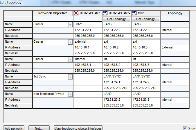

And now to the "Topology tab"
 |
| Topology anti-spoofing config |
4. Create a simple group and include all four subnets:

5. Now, go back to the topology anti-spoofing config in step 3 and modify it to use the group you created.

There, anti-spoofing should work correctly. Make sure NAT is configured properly!
Checkpoint UTM Firewall Clusters Part 1
I recently spent some time setting up a Checkpoint Firewall cluster using UTM firewall appliances. I'm going to post several configuration tips I learned the hard way. I did not find the documentation to be all that useful, though I was in a bit of a rush, so I might have missed something.
Anyway, I'm laying out the topology in this post. Here are our nets:
Note that there is a layer 3 switch behind the inside interface on the Checkpoint cluster, and that at least three VLAN/subnets are behind that switch. Note that there is an IPSec tunnel to the co-lo facility, and that tunnel terminates on the L3 switch in the router network (the endpoint is 192.168.5.200.)
Here is a simple diagram of the configuration:

Anyway, I'm laying out the topology in this post. Here are our nets:
| Interface Name | Subnet | Comments |
| ext | 10.10.10.0/24 | external network |
| int | 192.168.5.0/24 | router net |
| LAN1 | 172.31.24.0/28 | sync network |
| LAN2 | 172.31.23.0/24 | network management subnet |
| LAN3 | 172.31.22.0/24 | DMZ1 |
| N/A | 192.168.6.0/23 | Corporate LAN (behind L3 switch) |
| N/A | 192.168.8.0/23 | Engineering LAN (behind L3 switch) |
| N/A | 192.168.10.0/23 | QA LAN (behind L3 switch) |
| N/A | 172.17.16.0/22 | subnet from CO-LO - from VPN tunnel |
Note that there is a layer 3 switch behind the inside interface on the Checkpoint cluster, and that at least three VLAN/subnets are behind that switch. Note that there is an IPSec tunnel to the co-lo facility, and that tunnel terminates on the L3 switch in the router network (the endpoint is 192.168.5.200.)
Here is a simple diagram of the configuration:

Subscribe to:
Posts (Atom)